ソフトウエア系のキーロガーはセキュリテーソフトに引っかかってしまいます。
ですので、今回面白い記事を見つけたので紹介します。
このサイトでは、ハードウエア的なキーロガーの作り方について紹介されています。
作り方について、エキサイト翻訳で翻訳してみました。
http://www.keelog.com/diy.html
原文
Open source DIY hardware keylogger
KeeLog has decided to release an early version of it’s hardware keylogger family to the public domain, including full firmware & software source code, keylogger hardware electrical schematics, and documentation. This PS/2 key logger is a 100% operational and tested device, assembled and used by hundreds of people around the world. Operation of this hardware key logger is similar to the KeeLoggerTM Classic. We provide the application KeyGrab for retrieve and analysis of recorded keystroke data. However, please note that this DIY hardware keylogger project is provided as is, with all faults, and with no warranty whatsoever.
![]()
Open source DIY hardware keylogger
Tools and components
Before you start, go down this list to check if you have all the tools and skills needed to accomplish this hardware keylogger project:
* some experience in electronics hardware
* a soldering iron
* a microcontroller programmer (supporting the Atmel AT89CXX51 family)
Open source DIY hardware keylogger – components The following components are required for the hardware keylogger project:
* Atmel AT89C2051 microcontroller (or AT89C1051, AT89C4051)
* AT24C512 serial EEPROM chip (or compatible)
* 12 MHz crystal
* 2 x 33p capacitor
* 10 uF capacitor
* 10 k resistor
* small push-button
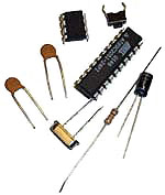
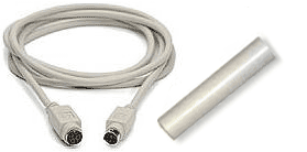
Open source DIY hardware keylogger – PS/2 cableFinally, casing for the hardware keylogger is required. A good idea is to buy a PS/2 extension cable and a 4-inch piece of heat-shrinkable tubing, which can be thermally wrapped around the ready made keylogger.
Put it together
Program the keylogger microcontroller firmware first. Start your programmer software, pick the AT89C2051, and burn the flash with the binary file or the hex version. You may also recompile the source using the source code and an 8051 compiler.
Soldering is probably the most difficult part of the project, as the keylogger hardware should be made as small as possible. The keylogger hardware schematics below show how connections should be made between components.
Open source DIY hardware keylogger – Tools and components
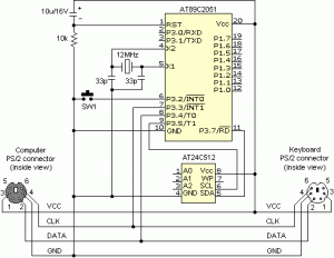
Solder the components together starting from the microcontroller and the EEPROM. Unused IC pins can be removed. Make sure the push button is accessible. When mounting the capacitor, make sure it’s biased correctly.
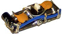
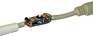
Open source DIY hardware keylogger – soldering Make the hardware keylogger as compact as possible, however avoid short circuits. They will be difficult to remove after the device is finished. The keylogger circuit should look somewhat like the prototype shown on the photo, after the main components are connected.
Finally, solder the PS/2 connectors to the keylogger. A good idea is to cut the PS/2 extension cable into two pieces and solder each part separately. Make sure you put the heat shrink tubing on one part of the cable. Connect all four used PS/2 pins (CLK, DATA, VCC, and GND) on both connectors (at the keyboard and at the computer). Open source DIY hardware keylogger – connectors
Before pulling the thermal tubing around the hardware keylogger, a good idea is to let some glue or resin in between the components, to make the device more rigid. Finally pull the thermal tubing on, heat it until it wraps around the soldered components, and cut out a small hole so the button is accessible.
Open source DIY hardware keylogger
Record mode
The hardware keylogger starts recording key data once plugged between the keyboard and the computer. The keylogger is completely transparent for computer operation and cannot be detected by software in record mode. All key data sent by the keyboard will be recorded to 64 kB hardware non-volatile EEPROM memory. Record mode is completely independent from the operating system installed on the computer.
Find the PS/2 connector at the computer. DIY hardware keylogger – install 1
Disconnect the keyboard. DIY hardware keylogger – install 2
Connect the hardware keylogger in place of the keyboard. DIY hardware keylogger – install 3
Connect the keyboard to the keylogger. On computer power-up data will start recording. DIY hardware keylogger – install 4


Playback mode
Once the hardware keylogger has recorded key data, it can be retrieved to any PC running Windows 9X/Me/XP/2000. The hardware keylogger does this by simulating keyboard keystrokes. The transmitted keystroke data is acquired by a the KeyGrab application. Once this data has been transmitted to the computer, it can be processed and analyzed. Follow the instructions for initiating data download.
Run the KeyGrab application. Open source DIY hardware keylogger – Record mode
Connect the hardware keylogger instead of the keyboard. Do not connect the keyboard. Open source DIY hardware keylogger – Record mode
Click on the KeyGrab title bar to make it the active application. Open source DIY hardware keylogger – Record mode
Press the button on the hardware keylogger to initiate data download. Do not change the active application during transmission. Press the button again to finish transmission. Do this when the desired keystroke data has been downloaded to the PC. Open source DIY hardware keylogger – Record mode
Disconnect the hardware keylogger and plug your PS/2 keyboard back in. Open source DIY hardware keylogger – Record mode


Data analysis
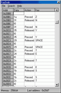
When downloading keystroke data to the KeyGrab main table, it’s automatically preprocessed to show key data that logged during recording. Data is transmitted in descending order, to show keys pressed recently first. Keystrokes that occurred a long time ago are transmitted later. You can analyze the table manually, or use some of the search options.
Open source DIY hardware keylogger – Data analysis
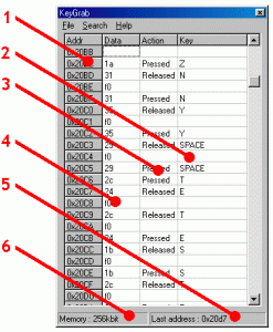
1 Position in keylogger hardware memory used by keyboard event (hex form).
2 Captured and logged keystroke.
3 Event that took place – a key press or release.
4 Keystroke scancode on PS/2 bus (hex form).
5 Last memory position written during recording (hex form).
6 Keylogger hardware memory size (in kilobits).
The only column that is of any interest to the user is Key (2) and Action (3). These columns code what keys have been pressed and released. Scroll the bar to see the keystroke history during recording. Keylogger data is transmitted in reverse chronological order (recent keystroke data first).
Download
The DIY hardware keylogger data retrieve and analysis application for Windows 9X/ME/2000/XP:
KeyGrab.zip (0.7MB)
The full source code for the AT89C2051 microcontroller:
Source code – diy.asm
The precompiled AT89C2051 hardware keylogger firmware is also available:
BIN file – diy.bin
HEX file – diy.hex
Open source DIY hardware keylogger – KeyGrab
Things you should know
We encourage you to read this section to avoid problems that might occur using the hardware keylogger.
Legal liability
1. Countries have different laws about logging keyboard data. Not knowing the law does not allow you not to obey it. Please read our user agreement.
2. We do not take any responsibility for any damage or harm caused by the use of this hardware keylogger.
3. You should not use this device to intercept data you are not authorized to possess, especially passwords, banking data, confidential correspondence etc. Most countries recognize this as a crime.
Key data logging
1. The hardware keylogger has 64 kB of non-volatile EEPROM memory. When this memory is full, writing will start over again from the first memory location. The oldest data will be lost.
2. The first 128 bytes of memory are reserved for configuration data, such as saving the last memory access address. The last memory access address is updated approximately every 10 seconds.
3. Do not leave the hardware keylogger connected in record mode when unnecessary. This will use memory and cause old, sometimes important, data to be overwritten.
Key data transmission
1. For keystroke data retrieve you will need at least a 100 MHz Pentium class computer with Windows 9X/Me/XP/2000 installed.
2. The hardware keylogger transmits data back to the computer simulating the keyboard. The real keyboard has to be disconnected during transmission.
3. The active application must be KeyGrab. In any other case, either Windows or a different application will start interpreting the simulated keystrokes coming from the hardware keylogger.
4. Keystroke data is retrieved in reverse chronological order. This is to provide recent data first. You have to wait a while to get very old keyboard data. The whole transmission process can last up to 20 minutes.
5. Transmission must be terminated manually by pressing the push-button again. Do this when the keystroke data starts getting duplicated.
PS/2 keyboard operation
1. The PS/2 keyboard is a bit more complicated than you might think. You can notice this analyzing raw data logged by the hardware keylogger. The PC keyboard generates one character each time a key is pressed. When the key is released, the character is generated again with a preceding 240 (F0 hex) character. There are also extended keys using the 224 (E0 hex) character. You can read about this in the short The PS/2 keyboard protocol.
2. Although the hardware keylogger has 64 kB of memory, this doesn’t mean 64 thousand keystrokes can be memorized. One key-press-release sequence requires 3 bytes for a standard key and 5 bytes for an extended key. Logging has been optimized in the commercial versions.
The PS/2 keyboard protocol
Background
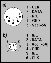
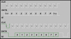
Open source DIY hardware keylogger – PS/2 signal lines If you were to cut a PS/2 keyboard cable through, you would probably find 6 wires within. Only 4 of these are meaningful. Two of these are power lines: ground (GND) and +5 volts (VCC) from the computer power supply. The other two wires are asynchronous transmission lines: the data line (DATA) and the clock line (CLK). You can see how these lines correspond to DIN (a) and miniDIN (b) connector pins on the figure to the right. Transmission is bi-directional, however the keyboard is superior. The keyboard sends information about keys which have been pressed and released. The data chunk consists of only one byte, preceded with a starting bit, and followed by a parity and stop bit. The keyboard puts successive bits on the DATA line, and clocks them with negative impulses on the CLK line. Clock frequency is 10…30 kHz. This would be a very nice serial protocol if it wasn’t for the computer, which occasionally wants to send information to the keyboard. In such cases, the PC pulls the CLK line low for some time and waits for the keyboard to start generating impulses. When these impulses start, it clocks it’s own character in on the DATA line. You can see state diagrams of keyboard to host (a) and host to keyboard (b) transmission on the figure below. This protocol has of course a few exceptions, like interrupting a transmission, character repeat etc. However, these are very rare cases.
Open source DIY hardware keylogger – waveforms
Bus data
So what is actually transmitted through the keyboard lines? On startup both the keyboard and the computer send initialization data, informing that they are OK. When the computer is running normally, only the keyboard sends data. This is data about every event that took place. An event is considered a key being pressed or released. If a standard key is pressed, it’s so called “scancode” is sent. Every key has exactly one scancode, creating a map of scancodes. If a key is released, first the special byte 240 (F0 hex) is sent , then the keys scancode is sent. So a standard keystroke causes 3 characters to be sent down the line. If a key is held down for some time, it’s scancode will be generated constantly with the set repetition delay. When it’s finally released, the 240 (F0 hex) character will be sent, followed by the scancode.
This would still be a nice protocol if it wasn’t for some special keys present on the standard PC keyboard, like Home, End, the arrows, etc. When a special key is pressed, the byte 224 (E0 hex) is generated, followed by the scancode. When a special key is released, the sequence 224, 240 is fired (E0, F0), followed by the scancode. Normal and special keys are common for all national keyboard layouts with regard to the map of scancodes. To make to story a bit more complicated, two super-special keys exist, Print Screen and Pause, which cause a whole sequence of scancodes to be transmitted. For a keyboard interfacer, it’s best to pretend these keys do not exist.
Data logging
The microcontroller monitors the DATA and CLK lines all the time, acquiring all data. Data is logged to non-volatile EEPROM memory as it goes down the line. Thanks to this, the user can later find out about every event on the keyboard.
When the user decides recording is over and presses the button, the hardware keylogger switches to playback mode. The keyboard should be disconnected, otherwise it will interpret the data flow. The keylogger starts simulating key data from internal hardware memory. The KeyGrab application has to be active, to process the flow of data from the keylogger hardware. Normal keys are simulated as they were written in memory, and special keys are transmitted using a two-byte hex code.
翻訳
オープンソースDIYハードウェアkeylogger
KeeLogは、それのハードウェアkeyloggerファミリーの早めのバージョンを公共の場にリリースすると決めました、完全なファームウェア、ソフトウェアソースコード、keyloggerのハードウェアの電気結線図、およびドキュメンテーションを含んでいて。 このPS/2キー・ロガーは世界中の何百人もの人々によって組み立てられて、使用された100%の操作上の、そして、テストされたデバイスです。 このハードウェアキー・ロガーの操作はKeeLoggerTM Classicと同様です。 私たちがアプリケーションKeyGrabを提供する、検索、そして、記録されたキーストロークデータの分析。 しかしながら、すべての欠点、およびどんな保証もいかなるでもあるそのままでこのDIYハードウェアkeyloggerプロジェクトを提供しません。
オープンソースDIYハードウェアkeylogger
ツールとコンポーネント
あなたが始める前に、このリストを下って、すべてのツールがあって、技能が、このハードウェアkeyloggerプロジェクトを達成する必要だったかどうかチェックしてください:
* エレクトロニクスハードウェアの何らかの経験
* はんだごて
* マイクロコントローラのプログラマ(アトメルAT89CXX51ファミリーを養います)
オープンソースDIYハードウェアkeylogger–、コンポーネント、次のコンポーネントがハードウェアkeyloggerプロジェクトに必要です:
* アトメルのAT89C2051マイクロコントローラ(または、AT89C1051、AT89C4051)
* AT24C512シリアルEEPROMチップと(コンパチブル)です。
* 12MHzの水晶
* 2x33pコンデンサー
* 10uFコンデンサー
* 10k抵抗体
* 小さい押しボタン
オープンソースDIYハードウェアkeylogger–PS/2cableFinally、ハードウェアkeyloggerのためのケーシングが必要です。 名案がPS/2拡大ケーブルと4インチの片の熱-縮小可能管材料を買うことであり、熱で準備ができるのにどれを巻きつけることができるかはkeyloggerを作りました。
それをまとめてください。
最初に、keyloggerマイクロコントローラファームウェアをプログラムしてください。 プログラマソフトウェアを始動してください、そして、AT89C2051を選んでください、そして、バイナリーファイルか十六進法バージョンでフラッシュを燃やしてください。 また、あなたは、ソースコードと8051年のコンパイラを使用することでソースを再コンパイルできます。
はんだ付けはたぶんプロジェクトの最も難しい部分です、keyloggerハードウェアをできるだけ小さくするべきであるとき。 以下のkeyloggerハードウェア結線図は接続がコンポーネントの間でどう作られているべきであるかを示しています。
オープンソースDIYハードウェアkeylogger–ツールとコンポーネント
マイクロコントローラとEEPROMから始めて、コンポーネントを一緒にはんだ付けしてください。 未使用のICピンを取り外すことができます。 押しボタンがアクセスしやすいのを確実にしてください。 コンデンサーを取り付けるときには、それが正しく偏られるのを確実にしてください。
オープンソースDIYハードウェアkeylogger–、はんだ付けMake、コンパクトな可能なハードウェア同じくらいkeylogger、しかしながら、避ける、短絡します。 デバイスが完成していた後に取り外すのはそれらが難しくなるでしょう。 keylogger回路は主なコンポーネントが接続されていた後にフォトに示されたプロトタイプにいくらか似ているはずです。
最終的に、PS/2コネクタをkeyloggerにはんだ付けしてください。 名案は、別々にPS/2拡大ケーブルを2つの断片に切って、各部分をはんだ付けすることです。 熱の精神科医管材料をケーブルの一部に必ず置いてください。 両方のコネクタ(キーボードにおけるコンピュータの)の上のすべての4本の中古のPS/2ピン(CLK、DATA、VCC、およびGND)を接続してください。 オープンソースDIYハードウェアkeylogger–コネクタBeforeがハードウェアkeyloggerの周りに熱管材料を引いて、名案はデバイスをより堅くするようにコンポーネントの間で、ある接着剤か樹脂を入れることです。 最終的に、熱管材料を引いて、オンにし、ハンダ付け部品を巻きつけるまで、それを加熱してください、そして、ボタンがアクセスしやすいようにわずかなホールを切り取ってください。
オープンソースDIYハードウェアkeylogger
レコード・モード
ハードウェアkeyloggerはキーボードとコンピュータの間で一度ふさがれた重要なデータを記録し始めます。 keyloggerはコンピュータ操作に完全に透明であり、レコード・モードによるソフトウェアで検出できません。 キーボードによって送られたすべての重要なデータが64のkBのハードウェアの非揮発性のEEPROM記憶に記録されるでしょう。 レコード・モードはコンピュータにインストールされたオペレーティングシステムから完全に独立しています。
コンピュータでPS/2コネクタを見つけてください。 DIYハードウェアkeylogger–1Disconnectをインストールしてください。キーボード。 DIYハードウェアkeylogger–2Connectをインストールしてください。キーボードに代わったハードウェアkeylogger。 DIYハードウェアkeylogger–3Connectをインストールしてください。keyloggerへのキーボード。 コンピュータパワーアップするのを、データは記録し始めるでしょう。 DIYハードウェアkeylogger–4をインストールしてください。
再生モード
ハードウェアがいったんより多くのkeyloggerに重要なデータを記録すると、どんなPCの実行しているWindows9X/にもそれを検索できる、私、/XP/2000 ハードウェアkeyloggerは、キーボードキーストロークをシミュレートすることによって、これをします。 伝えられたキーストロークデータはKeyGrabによって取得されます。アプリケーション。 このデータがいったんコンピュータに送られると、それを処理して、分析できます。 データダウンロードを開始するための指示に従ってください。
KeyGrabアプリケーションを実行してください。 オープンソースDIYハードウェアkeylogger–、レコード・モードConnect、キーボードの代わりにハードウェアkeylogger。 キーボードを接続しないでください。 オープンソースDIYハードウェアkeylogger–それを選考中の応募者にするKeyGrabタイトルバーに関するレコード・モードクリック。 オープンソースDIYハードウェアkeylogger–開始データへのハードウェアkeyloggerの上のボタンがダウンロードするレコード・モードPress。 トランスミッションの間、選考中の応募者を変えないでください。 もう一度ボタンを押して、トランスミッションを終えてください。 必要なキーストロークデータをPCにダウンロードしたときにはこれをしてください。 オープンソースDIYハードウェアkeylogger–、レコード・モードDisconnect、あなたのPS/2がキーボードを操作するハードウェア的なkeyloggerとプラグはコネを支持します。 オープンソースDIYハードウェアkeylogger–レコード・モード
データ分析
キーストロークデータをKeyGrab主卓にダウンロードするとき、それは自動的にショー重要データとして録音の間に登録されたそれを前処理しました。 データは、キーが最初に最近押されたのを示すために降順に送られます。 昔に起こったキーストロークは後で伝えられます。 あなたは、手動でテーブルを分析するか、または検索オプションのいくつかを使用できます。
オープンソースDIYハードウェアkeylogger–データ分析
1 keyloggerでは、キーボードイベント(十六進法フォーム)でメモリが使用したハード
ウェアを置きます。
2 キーストロークを得て、登録しました。
3 行われたイベント–主要なプレスかリリース。
4 PS/2の上のキーストロークscancodeは(十六進法フォーム)をバスで運びます。
5 (十六進法フォーム)を記録している間に書かれた最後のメモリ位置。
6 Keyloggerハードウェア記憶容量(キロビットにおける)。
ユーザにいずれおもしろい唯一のコラムが、Key(2)とAction(3)です。 これらのコラムはキーが持っている押されて、リリースされたものをコード化します。 バーをスクロールして、録音の間、キーストローク歴史を見てください。 Keyloggerデータが新しい順で送られる、(最近のキーストロークデータ、1番目)
ダウンロード
keyloggerデータが取るDIYハードウェアとWindows9X/ME/2000/XPの分析アプリケーション:
KeyGrab.zip(0.7MB)
AT89C2051マイクロコントローラにとって、完全なソースコード:
ソースコード–diy.asm
また、precompiled AT89C2051ハードウェアkeyloggerファームウェアも利用可能です:
BINファイル–diy.bin
HEXファイル–diy.hex
オープンソースDIYハードウェアkeylogger–KeyGrab
あなたが知るべきであること
私たちは、あなたがハードウェアkeyloggerを使用することにおける起こるかもしれない問題を避けるためにこのセクションを読むよう奨励します。
法的責任
1. 国には、伐採キーボードデータに関する異なった法があります。 法を知らないのに、あなたはそれに従わないことができません。 私たちのユーザ同意を読んでください。
2. 私たちはこのハードウェアkeyloggerの使用でもたらされたどんな損害や害への少しの責任も取りません。
3. あなたは所有するために認可されていなくデータを傍受するのにこのデバイスを使用するべきではありません、特にパスワード、通信の秘密のデータなどを盛り土して ほとんどの国が、これが犯罪であると認めます。
重要なデータ伐採
1. ハードウェアkeyloggerには、非揮発性のEEPROM記憶の64kBがあります。 このメモリが完全であるときに、書くことは最初の記憶域から最初からやり直すでしょう。 最も古いデータは失われるでしょう。
2. 最初の128バイトのメモリは最後のメモリがアクセスアドレスであると保存することなどのコンフィギュレーション・データのために予約されます。 10秒毎に最後のメモリアクセスアドレスをアップデートします。
3. 不要であるときにレコード・モードで接続されたkeyloggerにハードウェアを残しません。 これで、メモリを使用して、古くて、時々重要なデータを上書きするでしょう。
重要なデータ送信
1. キーストロークデータが検索する、あなたがWindows9X/と共に少なくとも100MHzのPentiumクラスコンピュータを必要とするために望んでいる、私、XP/2000がインストールした/。
2. ハードウェアkeyloggerはキーボードをシミュレートするコンピュータにデータを送って戻します。 実際のキーボードトランスミッションの間、切断されなければなりません。
3. 選考中の応募者はKeyGrabであるに違いありません。 いかなる他の場合ではも、Windowsか異なったアプリケーションのどちらかがハードウェアkeyloggerから来るシミュレートされたキーストロークを解釈し始めるでしょう。
4. キーストロークデータは新しい順で検索されます。 これは、最初に最近のデータを提供するためのものです。 あなたは、しばらく非常に古いキーボードデータを得るのを待たなければなりません。 全体のトランスミッションプロセスは最大20分続くことができます。
5. 再び押しボタンを押すことによって、手動でトランスミッションを終えなければなりません。 キーストロークデータがコピーさせ始めるとき、これをします。
PS/2キーボード操作
1. PS/2キーボードはあなたが思うかもしれないより複雑です。 あなたは生データがハードウェアkeyloggerで登録したこの分析に気付くことができます。 PCキーボードは、1つのキャラクタがキーが押される各回であると生成します。 キーがリリースされるとき、キャラクタは再び前の240(F0十六進法)キャラクタと共に生成されます。 また、224(0ユーロの十六進法)キャラクタを使用する拡張キーがあります。 あなたは不足するところでPS/2キーボードが議定書の中で述べるこれに関して読むことができます。
2. ハードウェアkeyloggerにはメモリの64kBがありますが、これは64を意味しません。1,000のキーストロークは暗記できます。 1つの主要なプレスリリース系列が標準のキーのための3バイトと拡張キーのための5バイトを必要とします。 伐採は商業バージョンで最適化されました。
PS/2キーボードプロトコル
バックグラウンド
オープンソースDIYハードウェアkeylogger–PS/2は、PS/2キーボードケーブルを深く切るようにあなたが系列Ifであったのに合図します、とあなたは中でたぶん6本のワイヤがわかるでしょう。 これらの4だけが重要です。 これらの2は電力系列です: コンピュータ電源から(GND)と+5ボルト(VCC)を地面に置いてください。 他の2本のワイヤが非同期伝送系列です: データライン(DATA)と時計は(CLK)を裏打ちします。 あなたはこれらの系列がどう図のDIN(a)とminiDIN(b)コネクタピンに対応するかを右に見ることができます。 トランスミッションが双方向である、しかしながら、キーボードは優れています。 キーボードは押されて、リリースされたキーの情報を送ります。 データ塊は始めのビットで先行されて、同等とストップビットがあとに続いた1バイトだけから成ります。 キーボードは、連続したビットをDATA系列に置いて、否定的衝動がCLK系列にある状態で、それらを時間を計ります。 クロック周波数は10です…30kHz コンピュータ(時折情報をキーボードに送りたがっている)がないなら、これは非常に良い連続のプロトコルでしょうに。 そのような場合、PCは、しばらくCLK系列安値を引いて、キーボードが衝動を生成し始めるのを待っています。 これらの衝動が始まるとき、それはDATA系列で自己のキャラクタの仕事を始めます。 あなたは、キーボードの州のダイヤグラムをホスト(a)に見て、以下の図の上でキーボード(b)にトランスミッションを主催できます。 このプロトコルには、キャラクタ反復トランスミッションなどを中断するようないくつかの例外がもちろんあります。 しかしながら、これらは非常にまれなケースです。
オープンソースDIYハードウェアkeylogger–波形
バスデータ
それで、何が実際にキーボード系列を通して伝えられますか? キーボードとコンピュータの両方が初期化データを送る始動では、それを知らせて、それらはOKです。 コンピュータが通常動いているとき、キーボードだけがデータを送ります。 これは行われたあらゆるイベントに関するデータです。 イベントは、押されて、キーであると考えられるか、またはリリースされます。 標準のキーが押されるなら、それが非常に呼ばれるので、”scancode”を送ります。 あらゆるキーには、scancodesの地図を作成して、ちょうど1scancodeがあります。 キーをリリースするなら、最初に、特別なバイト240(F0十六進法)を送って、その時はscancodeが送られるキーです。 それで、標準のキーストロークで、3つのキャラクタを系列の下側に送ります。 キーがしばらく押さえられるなら、scancodeが絶えずセット反復遅れで生成されるということです。 最終的にそれをリリースするとき、scancodeによって続かれて、240(F0十六進法)キャラクタを送るでしょう。
ホーム、End、矢のような標準のPCキーボードの現在のいくつかの特別なキーなどがないなら、これはまだ良いプロトコルでしょうに。 特別なキーが押されるとき、scancodeによって続かれて、バイト224(0ユーロの十六進法)は発生しています。 特別なキーがリリースされるとき、scancodeによって続かれて、系列224、240は適用されます(0E、F0)。 すべての国家の鍵盤配列に、正常で特別なキーはscancodesの地図に関して一般的です。 Print ScreenとPause、キーをもう少し複雑にされた話、2スーパースペシャルにするように、存在してください、scancodesの全体の系列を伝えるどれ。 キーボードinterfacerに関しては、これらのキーが存在しないふりをするのは最も良いです。
データ記録
すべてのデータを取得して、マイクロコントローラは絶えず、DATAとCLK系列をモニターします。 系列を下っている間、データは非揮発性のEEPROM記憶に登録されます。 これのおかげで、ユーザは後でキーボードの上のあらゆるイベントを見つけることができます。
ユーザが録音が終わっていると決めて、ボタンを押すと、ハードウェアkeyloggerは再生モードに切り替わります。 キーボード切断されるべきです。さもなければ、それはデータフローを解釈するでしょう。 keyloggerは内部のハードウェア記憶からの重要なデータをシミュレートし始めます。 KeyGrabアプリケーションは、アクティブであり、keyloggerハードウェアからデータの流れを処理しなければなりません。 それらがメモリに書かれたように正常なキーはシミュレートされます、そして、特別なキーは、2バイトの十六進法コードを使用することで送られます。
0 Comments.